First Week Update
We focused on the audio input part during first week. The LPC4088 board has an on-board audio codec UDA1380 which is driven by I2S interface. We figured out how the I2S interface works and config the UDA1380 to take sound input from the microphone.
The I2S interface works in interrupt mode and each time UDA1380 detects a sound input, the handler will be triggered and take a short period of sound signal input and store the amplitude value in to a buffer. The microphone is very sensible so the buffer would store value due to background noices. For our project, we want the audio codec to distinguish the user sound input from those random background noice. As a solution, we apply an amplitude filter. It would add up all the absolute values in the buffer and sum them up. We took sever test trial and set a boundary value. If the sum value is larger than this boundary value, the input would be recognized as a input.
The I2S interface works in interrupt mode and each time UDA1380 detects a sound input, the handler will be triggered and take a short period of sound signal input and store the amplitude value in to a buffer. The microphone is very sensible so the buffer would store value due to background noices. For our project, we want the audio codec to distinguish the user sound input from those random background noice. As a solution, we apply an amplitude filter. It would add up all the absolute values in the buffer and sum them up. We took sever test trial and set a boundary value. If the sum value is larger than this boundary value, the input would be recognized as a input.
Second Week Update
We focused on the LCD output during second week. Our initial plan was to use the ILI9340 LCD which is driven by SPI interface. However, we were not able to light up the LCD since we could not how SPI works on LPC4088 board. Finally we decided to switch from an LCD screen to a LED matrix driven by I2C interface.
The LED matrix we got is designed for arduino boards so we have to start from the data sheet. We figured out to control the LED matrix we need to know its slave address and let the master device to send a hexadecimal number to the I2C write buffer which LED matrix would recognize as "instruction". However, from the data sheet, we were only able to figure out how to light up the LED matrix, set up the oscillation (the inner clock of the LED matrix), and change between blinking and stable mode. We were not able to get the pattern we want on the LED.
The LED matrix we got is designed for arduino boards so we have to start from the data sheet. We figured out to control the LED matrix we need to know its slave address and let the master device to send a hexadecimal number to the I2C write buffer which LED matrix would recognize as "instruction". However, from the data sheet, we were only able to figure out how to light up the LED matrix, set up the oscillation (the inner clock of the LED matrix), and change between blinking and stable mode. We were not able to get the pattern we want on the LED.
Third Week Update
We continued working on the LED matrix this week. In order to control the LEDs to get the desired pattern, we tried to convert an arduino example code to work for LPC4088. After several tries, we figure out that we need a buffer contains two array. The first array stores a hexideciaml value which tells which row will be configured (for example 0x00 to control the first row, 0x02 to control the second row). The value in the second array tells which of the eight lights on the row would be light up. The master device will then send this write buffer to the LED matrix to light up a certain pattern. However, we can change the pattern one row each time.
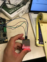
The picture shows the initial state, or the starting screen for our game. The two line on the bottom is our ground, and person is the two pixel on top of the ground. Since we can change only one row each time, we will have to write codes for each frame in order to make a moving object.
However, when we tried to combine the sound input code(I2s) and LED control code(I2C) together, there is only one
peripheral can work, either sound or LED.
Forth week Update
We tried to figure out how to combine the two part together during the last week. it turns out that the audio codec UDA1380 itself is driven by I2C first and the data it got is then transferred to I2S bus. And the UDA1380 is working in I2C interrupt polling mode which means it is constantly checking for interrupts and ignore everything else. That's the reason once the audio codec is working, the LED matrix would not light up. So we found the code for UDA1380 initiation and made configurations. Also we decided to enable the NVIC for I2S at the beginning of each frame and turns it off after a short delay so that the audio codec won't affect the moving of the object. We also add a button input to restart the game
Here is a demo video for our project. https://www.youtube.com/watch?v=rT02bN0vEFQ
Here is a demo video for our project. https://www.youtube.com/watch?v=rT02bN0vEFQ
